

 English
 русский
 Español


Cable stranding is the manufacturing process of helically twisting multiple individual conductors — typically copper or aluminum wires — together to form a single, unified cable core that delivers superior flexibility, conductivity, and mechanical strength compared to a single solid conductor of the same cross-sectional area. Used across power transmission, telecommunications, automotive wiring, aerospace, and industrial automation, cable stranding is one of the most fundamental and consequential steps in cable manufacturing. Understanding how stranding works, which patterns are available, and why each configuration matters is essential for engineers, procurement managers, and anyone specifying cables for demanding applications.
Content
- 1 How Does Cable Stranding Work?
- 2 Which Cable Stranding Configurations Are Most Widely Used?
- 3 Cable Stranding Configuration Comparison
- 4 Why Cable Stranding Matters: Solid Conductor vs. Stranded Conductor
- 5 How IEC 60228 Classifies Cable Stranding
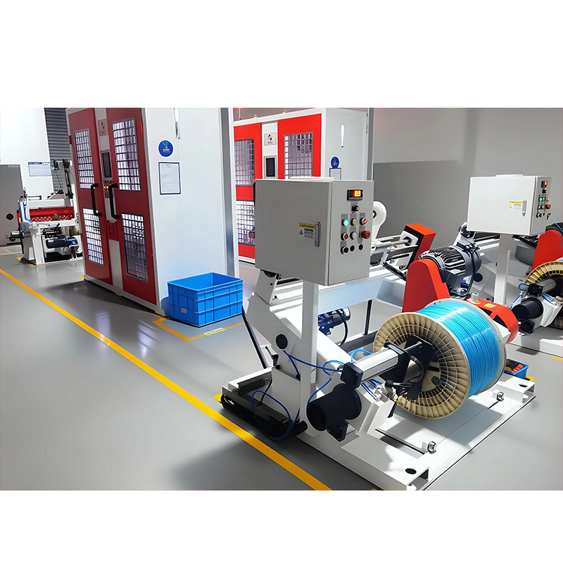
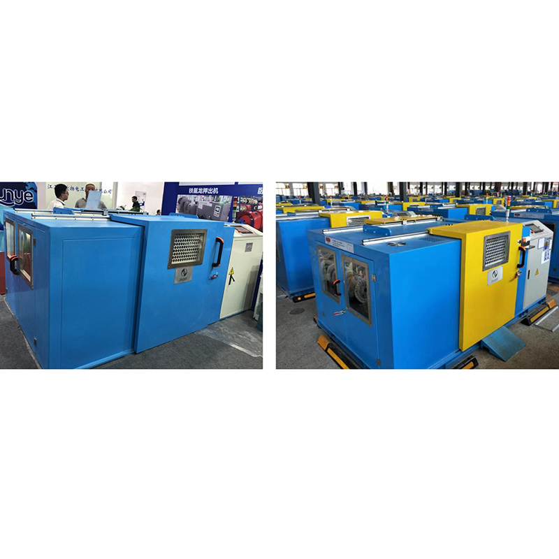
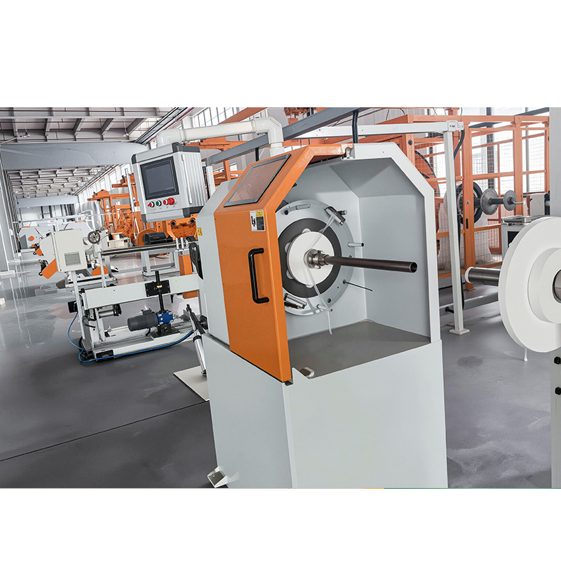
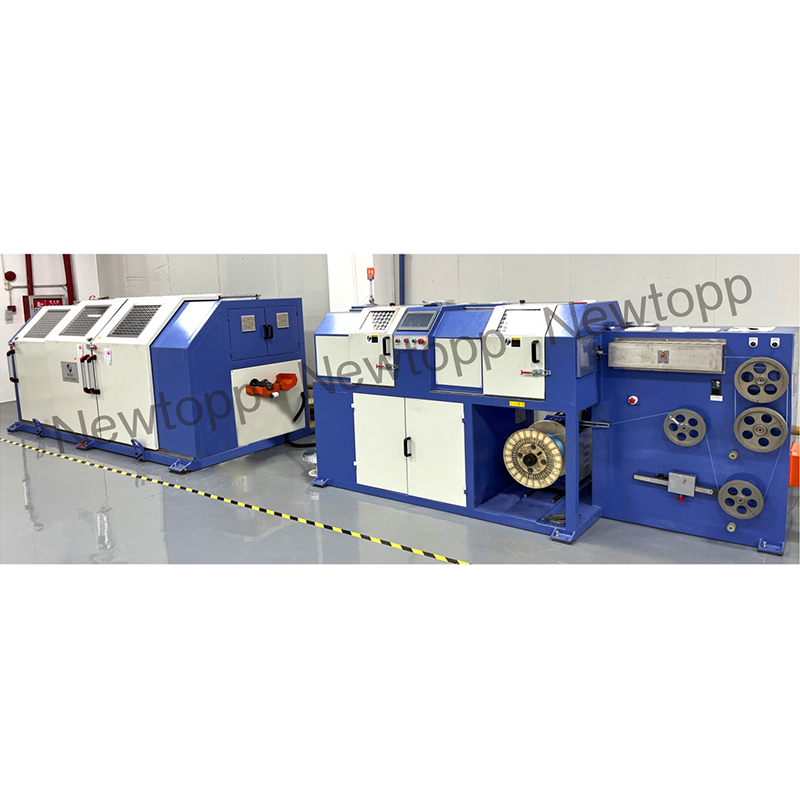
- 6 What Stranding Machines and Technologies Are Used in Production?
- 7 Why Lay Length and Pitch Angle Are Critical in Cable Stranding
- 8 How Cable Stranding Is Applied Across Key Industries
- 9 Frequently Asked Questions About Cable Stranding
- 9.1 Q: Does cable stranding affect current-carrying capacity (ampacity)?
- 9.2 Q: What is the difference between compressed and compacted stranding?
- 9.3 Q: Why do some stranded cables use aluminum instead of copper?
- 9.4 Q: How does cable stranding affect electromagnetic interference (EMI) shielding?
- 9.5 Q: What quality tests are performed on stranded cable conductors?
- 9.6 Q: What is Milliken stranding and when is it used?
- 10 Conclusion: Choosing the Right Cable Stranding for Your Application
How Does Cable Stranding Work?
Cable stranding works by feeding multiple individual wires simultaneously through a stranding machine that rotates them around a central axis in a controlled helical pattern, with the pitch length — the distance over which one complete twist occurs — precisely engineered to achieve the target flexibility, roundness, and electrical performance.
The process begins with individual wire drawing, where rod stock is pulled through progressively smaller dies to reach the specified wire gauge. These wires are then loaded onto bobbins or payoff reels and fed into the stranding machine. Depending on the stranding method, the machine either rotates the bobbins around a stationary take-up reel (planetary or tubular stranding) or keeps the bobbins stationary while the entire assembly rotates (rigid or cradle stranding).
Key process parameters that determine cable stranding quality include:
- Lay length (pitch): The axial distance for one complete helical turn. Shorter lay lengths increase flexibility but add length to each wire, increasing resistance slightly. IEC 60228 specifies lay length limits for each conductor class.
- Lay direction: Wires are twisted in either a right-hand (Z-lay) or left-hand (S-lay) direction. In multi-layer cables, alternating S and Z directions in successive layers prevents unraveling and internal stress buildup.
- Number of wires: Stranded cables follow geometric packing sequences — 7, 19, 37, 61, 91 wires — that allow perfect hexagonal packing of round wires and predictable cross-sectional area.
- Compaction ratio: After stranding, a compacting die or roller press can reduce the outer diameter by 5–15%, improving the fill factor and reducing insulation material requirements.
Which Cable Stranding Configurations Are Most Widely Used?
The most widely used cable stranding configurations are concentric stranding, bunch stranding, rope stranding, and sector stranding — each optimized for a different balance of flexibility, diameter, and ease of manufacture.
1. Concentric Stranding
Concentric stranding is the most common configuration in power cable manufacturing, consisting of a central wire surrounded by successive layers of wires in a hexagonal packing arrangement. Each added layer increases the wire count by 6: a 7-wire strand (1 center + 6), a 19-wire strand (1 + 6 + 12), a 37-wire strand (1 + 6 + 12 + 18), and so on. Concentric stranding produces a round, mechanically stable cable with predictable electrical characteristics and is specified in IEC 60228 Classes 1 and 2. It is the standard choice for power distribution cables, building wire, and overhead transmission conductors.
2. Bunch Stranding
Bunch stranding twists all wires simultaneously in the same direction without any geometric arrangement, producing the most flexible stranded conductors available at the cost of a less uniform cross-section. Because the wires have no fixed geometric position, bunch-stranded cables achieve maximum flexibility and are the preferred choice for portable cords, appliance wiring, audio cables, and fine-wire instrumentation cables. IEC 60228 Class 5 and Class 6 conductors are typically bunch stranded, with Class 6 using finer individual wire diameters — as small as 0.05 mm — for ultra-flexible applications.
3. Rope Stranding
Rope stranding assembles multiple pre-stranded sub-conductors (called "strands" or "groups") together in a second stranding operation, creating a large-diameter, high-flexibility conductor suitable for very large cross-sectional areas. This configuration is standard for large power cables above 300 mm², welding cables, mining cables, and offshore umbilicals where both very high current-carrying capacity and resistance to dynamic bending fatigue are required. Rope-stranded conductors can contain hundreds or even thousands of individual wires.
4. Sector Stranding
Sector stranding shapes the stranded conductor into a sector (pie-slice) cross-section rather than a circle, allowing three- or four-core cables to be assembled with a significantly smaller overall cable diameter compared to round conductors of the same cross-section. A three-core cable using sector-shaped conductors typically achieves an outer diameter reduction of 10–15% versus round conductors, directly reducing material costs for sheathing, armor, and installation conduit. Sector stranding is standard in medium-voltage power distribution cables.
Cable Stranding Configuration Comparison
| Configuration | Flexibility | Cross-section Uniformity | Typical IEC Class | Primary Application |
| Concentric | Low - Medium | Excellent | Class 1, 2 | Power distribution, building wire |
| Bunch | Very High | Fair | Class 5, 6 | Portable cords, appliances, audio |
| Rope | High | Good | Class 5, 6 | Welding, mining, offshore cables |
| Sector | Low - Medium | Good (non-round) | Class 2 | Medium-voltage multi-core power cables |
Table 1: Comparison of the four primary cable stranding configurations by flexibility, cross-section uniformity, IEC 60228 conductor class, and typical application.
Why Cable Stranding Matters: Solid Conductor vs. Stranded Conductor
Stranded conductors outperform solid conductors in virtually every dynamic application because the individual wires in a stranded cable can slide relative to each other during bending, distributing mechanical stress across the entire cross-section and preventing fatigue fracture that would quickly destroy a solid conductor.
When a solid conductor is bent repeatedly, all bending stress concentrates at a single outer fiber, leading to work hardening and eventual fatigue cracking — a process that can occur in as few as 1,000–5,000 flex cycles for a solid copper conductor of 1.5 mm diameter. A 7-wire concentric stranded conductor of the same cross-section can withstand 50,000–200,000 flex cycles under comparable conditions, while a fine-wire Class 6 bunch-stranded conductor may exceed 10 million cycles in optimized configurations.
Additional advantages of stranded over solid conductors include:
- Reduced skin effect at high frequencies: At frequencies above a few kilohertz, current crowds toward the outer surface of a conductor (the skin effect), increasing effective resistance. In stranded cables, each individual wire has a smaller radius, reducing skin-effect losses by 5–30% depending on frequency and wire gauge.
- Easier installation: Stranded cables can be routed through conduit, around corners, and through tight spaces that would buckle or kink a solid conductor.
- Fault tolerance: If one wire within a stranded conductor breaks, the remaining wires continue carrying current, reducing the risk of sudden complete failure compared to a solid conductor.
- Better termination compression: Stranded conductors compress and deform more uniformly in crimp terminals, producing lower-resistance and more reliable electrical joints than solid conductors of equivalent cross-section.
| Property | Solid Conductor | Stranded Conductor |
| Flexibility | Low | Medium to Very High (by class) |
| Flex Cycle Life | 1,000 - 5,000 cycles | 50,000 - 10,000,000+ cycles |
| DC Resistance | Slightly Lower | Slightly Higher (1 - 3%) |
| Skin Effect Loss | Higher at AC/HF | Lower (smaller individual wire radius) |
| Installation Ease | Moderate (rigid) | Easy (bendable) |
| Manufacturing Cost | Lower | Slightly Higher |
| Crimp Termination | Fair | Excellent |
Table 2: Side-by-side comparison of solid and stranded conductors across key electrical and mechanical properties.
How IEC 60228 Classifies Cable Stranding
IEC 60228 is the primary international standard governing stranded conductor classification, defining six conductor classes based on the number and diameter of individual wires, with higher class numbers indicating greater flexibility and finer individual wire gauges.
- Class 1 (Solid): Single solid conductor. Used for fixed installation in conduit or buried service where no bending occurs after installation.
- Class 2 (Stranded, fixed installation): Concentric stranded with relatively large individual wires. Used for fixed power wiring in buildings, substations, and underground distribution.
- Class 3 (Flexible, limited use): Not widely referenced in modern specifications; intermediate flexibility.
- Class 4 (Flexible): Stranded with more and finer wires than Class 2; suitable for cables that are moved occasionally during service.
- Class 5 (Flexible, portable): Fine-wire stranded, suitable for frequent flexing, portable tools, extension cords, and machine tool wiring.
- Class 6 (Extra flexible): Very fine individual wires (as small as 0.05 mm diameter); designed for continuous dynamic flexing, robotic cables, drag chains, and ultra-flexible specialty applications.
What Stranding Machines and Technologies Are Used in Production?
Modern cable stranding relies on four main machine types — tubular stranders, planetary stranders, rigid (frame) stranders, and skip stranders — each suited to specific conductor sizes, stranding patterns, and production speeds.
Tubular Stranders
Tubular stranders are the most common machine type for fine-wire and medium-wire stranding, capable of production speeds up to 2,000 meters per minute for small conductors. Wire bobbins are mounted inside a rotating tube, and the tube's rotation imparts the twist to the outgoing conductor. Tubular stranders are well-suited to concentric and bunch stranding of conductors up to approximately 150 mm².
Planetary Stranders
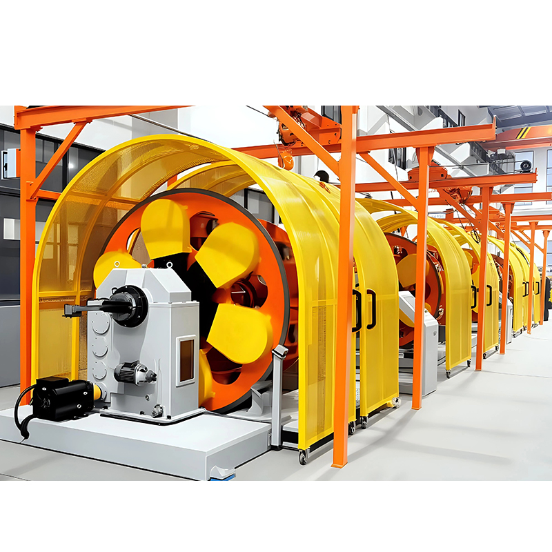
Planetary stranders keep the wire bobbins level (non-rotating) while the carrier frame revolves around the central axis, enabling stranding of large, heavy reels that cannot be rotated at high speed. They are the standard for large cross-section conductors (185 mm² to 2,500 mm²) used in overhead transmission lines, submarine cables, and large industrial power cables. Planetary stranders typically run at 30–150 rpm, producing lay lengths of 50–1,500 mm.
Rigid (Frame) Stranders
Rigid stranders rotate both the take-up spool and the entire frame, allowing very precise control of lay length and direction — making them the preferred choice for specialized telecommunications cables, data cables, and coaxial center conductors where electrical uniformity is critical.
Skip Stranders
Skip stranders, also called multi-twist or SZ stranders, alternate the twist direction periodically (SZ twisting) rather than continuously in one direction, allowing in-line operations such as screen application, filling, and sheathing without the need to rotate heavy downstream equipment. SZ stranding has become the dominant technology in modern high-speed data cable and fiber optic cable manufacturing, where production line integration and gentle handling of optical fiber are essential.
Why Lay Length and Pitch Angle Are Critical in Cable Stranding
Lay length is arguably the single most important variable in cable stranding engineering, because it directly controls the trade-off between flexibility, DC resistance, tensile strength, and cable diameter.
A shorter lay length means each wire follows a tighter helix, which:
- Increases wire length per unit of cable length — raising the conductor's effective DC resistance by typically 1–3% versus the theoretical cross-section.
- Increases flexibility and bending fatigue resistance.
- Increases tensile strength contribution from wire-to-wire interlock.
- Increases the cable's outer diameter slightly, requiring more insulation material.
Conversely, a longer lay length reduces resistance and diameter but increases stiffness and reduces the ability of wires to distribute bending stress. IEC 60228 specifies maximum lay lengths as a multiple of the stranded conductor diameter — for example, for a Class 2 conductor, the lay length must not exceed 16 times the outer diameter of the conductor layer.
In multi-layer concentric stranding, the lay length of each successive layer is typically set at 1.2–1.5 times that of the inner layer to maintain a consistent helix angle across layers, ensuring that the cable remains round and resists splitting under compression.
How Cable Stranding Is Applied Across Key Industries
Cable stranding specifications vary dramatically across industries, with each sector driving unique requirements for wire diameter, lay length, material purity, and conductor geometry.
Power Transmission and Distribution
Overhead transmission conductors such as ACSR (Aluminum Conductor Steel Reinforced) use concentric cable stranding with a steel core for tensile strength and outer aluminum layers for conductivity. A typical 400 kV ACSR conductor may contain 54 aluminum wires stranded in three concentric layers around a 7-wire steel core, with each layer stranded in alternating directions. The steel core provides a tensile strength of 100–200 kN while the aluminum outer layers carry the bulk of the electrical current.
Automotive Wiring
Automotive cables must withstand vibration, oil exposure, and temperature cycling from -40°C to +125°C over a vehicle lifetime exceeding 10 years. Fine-wire bunch and concentric stranded copper conductors in the 0.35 mm² to 4 mm² range are standard, with individual wire diameters of 0.1–0.25 mm. The shift to electric vehicles has driven significant growth in high-voltage cable stranding for battery, inverter, and motor connections, where cross-sections of 35–240 mm² and flexible Class 5 or Class 6 conductors are increasingly specified.
Data and Telecommunications
In data cables, cable stranding of individual twisted pairs controls crosstalk and electromagnetic interference. Each pair within a Cat6A or Cat8 Ethernet cable is individually twisted at a unique lay length (twist rate), typically between 12 and 25 mm, so that pairs do not align and inductively couple with each other. Precisely controlling lay length to within 1 mm tolerance is essential to meeting channel insertion loss and alien crosstalk limits defined in TIA-568 and ISO/IEC 11801.
Aerospace and Defense
Aerospace cable stranding follows MIL-W-22759 and AS22759 standards, requiring silver- or nickel-plated copper wires to prevent oxidation at high temperatures, and specifying extremely fine individual wire gauges (0.05–0.1 mm) for weight reduction. A 20 AWG aerospace cable rated for 260°C continuous service may contain 19 or 37 silver-plated copper wires in a concentric stranded configuration, providing the combination of heat resistance, flexibility, and weight that commercial cables cannot match.
Frequently Asked Questions About Cable Stranding
Q: Does cable stranding affect current-carrying capacity (ampacity)?
Stranded conductors have marginally higher DC resistance than solid conductors of the same nominal cross-section, which can reduce calculated ampacity by approximately 1–3%, but this difference is negligible in most practical sizing exercises. Cable ampacity tables in IEC 60364 and NEC 310 are based on the nominal conductor cross-section regardless of stranding class. At high frequencies (above 10 kHz), stranded conductors can actually show lower effective resistance than solid conductors of the same area due to reduced skin effect, giving stranded cables a distinct advantage in power electronics and high-frequency applications.
Q: What is the difference between compressed and compacted stranding?
Compressed stranding reduces the outer diameter of a standard concentric strand by approximately 3–5% by passing it through a closing die that slightly flattens the outermost wires, while compacted stranding uses a harder die or roller set to deform wires more significantly, reducing diameter by 8–15% and producing a near-solid outer surface. Compacted conductors have a higher fill factor, lower insulation material consumption, and slightly smoother surfaces that improve extrusion quality, making them the preferred choice in medium- and high-voltage cable production. The trade-off is a minor reduction in flexibility compared to non-compacted strands of the same cross-section.
Q: Why do some stranded cables use aluminum instead of copper?
Aluminum stranded conductors are used in overhead transmission lines, large underground power cables, and utility service entrance cables because aluminum weighs approximately one-third as much as copper, dramatically reducing structural support costs despite its lower conductivity. An aluminum conductor requires a cross-section roughly 1.6 times larger than copper to carry the same current, but the weight saving — aluminum is 2.7 g/cm³ versus copper's 8.9 g/cm³ — more than justifies the larger diameter for long-span overhead installations. Aluminum stranding also requires special termination connectors and anti-oxidation compounds to prevent galvanic corrosion at connection points.
Q: How does cable stranding affect electromagnetic interference (EMI) shielding?
Cable stranding of the shield layer — whether braid, serve, or spiral — directly controls the shield's coverage percentage, transfer impedance, and frequency response, with braided shields typically providing 85–98% coverage and spiral (serve) shields providing near-100% optical coverage but lower high-frequency performance. In signal cables, the stranding pitch of the inner conductors relative to the shield must be carefully coordinated to prevent resonant coupling. In power cables, concentric wire screens are stranded at a long lay length to maximize contact with the insulation screen while minimizing the screen's DC resistance.
Q: What quality tests are performed on stranded cable conductors?
Quality verification of cable stranding typically includes DC resistance measurement per IEC 60468, dimensional checks for outer diameter and lay length, wire count verification, tensile strength testing per IEC 60068-2-21, and flex life testing in accordance with the relevant cable standard. For automotive cables, additional tests include resistance to engine fluids, thermal shock, and vibration fatigue. For aerospace cables, surface plating thickness is verified by X-ray fluorescence (XRF) analysis. In high-voltage cable conductors, conductor concentricity and surface smoothness are verified to ensure defect-free insulation extrusion and to prevent electrical stress concentration points.
Q: What is Milliken stranding and when is it used?
Milliken stranding is a specialized cable stranding technique used exclusively for very large cross-section conductors (typically 1,000 mm² and above) in which the conductor is divided into 5 or 6 individually insulated, keystone-shaped segments that are stranded together to form the complete conductor, dramatically reducing skin effect and proximity effect losses at power frequencies. Without Milliken construction, a solid or conventional rope-stranded conductor above 1,200 mm² would experience AC resistance 20–35% higher than its DC resistance at 50 Hz, wasting significant energy. Milliken conductors are standard in large submarine power cables, generator bus bars, and high-capacity underground transmission cables where minimizing AC losses is economically critical.
Conclusion: Choosing the Right Cable Stranding for Your Application
Selecting the correct cable stranding configuration begins with three questions: How much flexibility does the cable need in service? What electrical performance — DC resistance, AC losses, or signal integrity — must be achieved? And what mechanical and environmental stresses will the cable face over its service life?
For fixed power installations, Class 1 or Class 2 concentric stranded conductors offer the lowest cost and highest conductivity per unit cross-section. For industrial machines, portable tools, and automotive harnesses, Class 5 fine-wire stranding delivers the flex life and installation ease the application demands. For large transmission infrastructure, sector stranding, Milliken construction, and ACSR designs address the unique combination of current capacity, mechanical strength, and AC loss management that no off-the-shelf configuration can simultaneously achieve.
As electrification accelerates across transportation, renewable energy, and industrial automation, cable stranding technology continues to evolve — with innovations in ultra-fine wire drawing, advanced compaction tooling, SZ stranding integration, and bio-based or recycled-content conductor materials pushing the boundaries of what stranded cables can deliver. Understanding the fundamentals of cable stranding remains as essential today as it was when the first telegraph wire was drawn and twisted more than a century ago.