

 English
 русский
 Español



Seven numbers decide whether a tubular stranding machine fits your conductor: bobbin count, bobbin size, pitch range, rotor speed, single-wire diameter, finished cross-section and per-bobbin tension accuracy. Everything else on a quotation is secondary, and a supplier who cannot quote all seven is guessing.
A tubular stranding machine is a rigid strander in which the pay-off bobbins sit inside a rotating tube. Each revolution of that tube lays exactly one twist into the conductor, so production speed and lay length are locked together by one formula: line speed equals pitch multiplied by rotor speed. There is no bow arm and no back twist, which keeps the wire path short, the windage low and the rotor fast. That combination is why tubular stranders carry most 7-, 19- and 37-wire bare copper and aluminium production up to roughly 630 mm².
If you are still mapping the wider machine family, a comprehensive guide to cable stranding machines is a useful companion to this page. Below we stay on tubular specifications and how to compare them line by line.
Content
- 1 What Is a Tubular Stranding Machine and When Is It the Right Tool?
- 2 The Specification Sheet: Eleven Numbers to Compare
- 3 Bobbin Count and Bobbin Size: Capacity in Plain Numbers
- 4 Pitch Range, Rotor Speed and Line Speed: Three Numbers That Interlock
- 5 Wire Range, Conductor Construction and Closing Dies
- 6 Tension Control, Take-Up and Drive System Specifications
- 7 Tubular vs Bow, Planetary and Back-Twist Stranders
- 8 What to Verify at Acceptance Testing
- 9 Procurement Risks and Site Requirements
- 10 FAQ: Tubular Stranding Machine Specifications
What Is a Tubular Stranding Machine and When Is It the Right Tool?
A tubular strander is the right tool when the construction calls for 7 to 37 wires, a concentric compact lay and continuous output, rather than the very large packages a planetary machine provides.
How the wire path works
Each pay-off bobbin sits in a cradle inside the rotating tube. Wire leaves the bobbin through a hollow spindle, runs over ceramic guide rollers, and all wires converge at a closing die immediately before the take-up capstan. Because the bobbins travel with the tube, the wire is released without being twisted back on itself, so the lay is formed only at the closing die. That is also why a tubular machine runs faster than a planetary strander with the same wire count: the rotating mass is a balanced cylinder instead of a large open cage.
Where a tubular strander is not the answer
Three cases push buyers elsewhere. Constructions beyond roughly 37 wires or 630 mm² usually need the larger bobbin capacity of a planetary strander. Insulated cores that tolerate two lays per revolution are better served by a bow-type double-twist machine, which halves the rotor speed needed for the same output. Data pairs and LAN cables need a back-twist pair strander so the individual conductors are not over-twisted before the pair is closed.
The Specification Sheet: Eleven Numbers to Compare
The specification sheet matters more than the brochure, because these eleven parameters describe what a tubular strander can actually produce rather than what it looks like on a factory floor.
| Parameter | Typical range | What it controls |
|---|---|---|
| Bobbin positions | 6+1 to 36+1 | Maximum number of wires in the finished conductor |
| Bobbin size | PND 400 to PND 800, larger on other strander types | Pay-off package volume and reload frequency |
| Pitch (lay length) range | 20 mm to 300 mm | Conductor flexibility and output at a given speed |
| Rotor speed | 200 to 1200 rpm | Ceiling on production speed at a given pitch |
| Line speed | 30 to 250 m/min | Output, but only meaningful when quoted with pitch |
| Single-wire diameter | 0.15 mm to 3.0 mm | What the tension system and guides can handle |
| Finished cross-section | 0.5 mm² to about 630 mm² | Conductor size the closing die and take-up accept |
| Per-bobbin tension | 5 N to 40 N, held within about ±10% | Concentricity, wire breaks and conductor ovality |
| Take-up bobbin | PND 630 to PND 1250 | Coil length handed to the next process |
| Pitch tolerance | Within about ±2% of set value | Lay-length consistency along the whole coil |
| Installed power | 15 kW to 75 kW | Site supply, cabling and foundation loading |
Bobbin Count and Bobbin Size: Capacity in Plain Numbers
Bobbin count sets the maximum wire count and bobbin size sets how long the machine runs before it stops for a reload, so nothing else on the data sheet changes daily output as much as these two figures.
Reading a bobbin count
A machine described as 12+1 has twelve rotating pay-off positions plus one stationary central position for the core wire. The pattern is straightforward: 6+1 builds a 7-wire conductor, 18+1 builds a 19-wire conductor and 36+1 builds a 37-wire conductor. Buy the count you need for the largest construction on your order book, because a machine cannot strand more wires than it has positions, and running a 19-wire job on a 36+1 machine wastes rotor capacity and energy.
Reading a bobbin size
Machine designations often carry the bobbin flange diameter, such as PND 400, 500, 630 or 800. Moving from a 400 mm to a 630 mm bobbin raises package volume by roughly two and a half times, since volume scales with the square of the diameter. That reduces reload stops on long runs, but the heavier tube needs more installed power, a stiffer foundation and longer braking distances. Where the conductor construction allows a larger package and a different twist geometry, machines such as the 1250 double-bow strander take the same logic up to a 1250 mm drum.
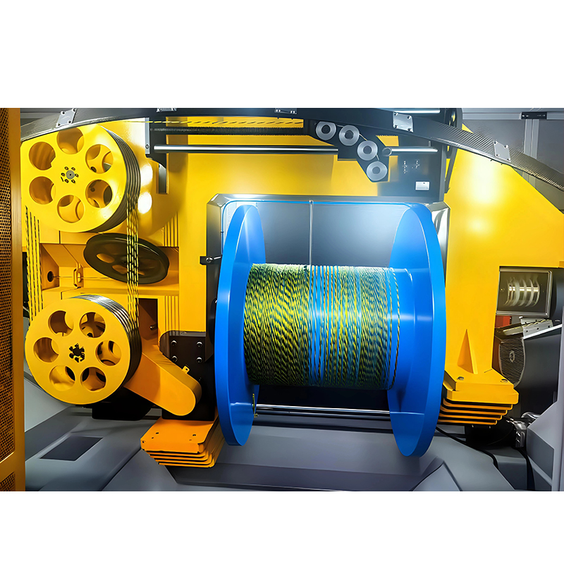 1250 Double Bow Stranding Machine for High-Speed Medium-Diameter Cable ProductionDouble-bow stranding machine with 1250 mm drum capacity, designed for balanced tension and high-speed stranding of medium-diameter conductors in data, power, and specialty cables.View Product →
Pitch Range, Rotor Speed and Line Speed: Three Numbers That Interlock
Pitch, rotor speed and line speed cannot be specified independently, because line speed in metres per minute is simply pitch in metres multiplied by rotor speed in revolutions per minute.
A 60 mm pitch at 800 rpm gives 48 m/min. The same machine at a 300 mm pitch and 830 rpm reaches 249 m/min — which is where the impressive headline figure usually comes from. When you compare quotations, convert every speed claim into a pitch and a rotor speed first; a machine advertised at 250 m/min may be incapable of your 60 mm pitch at more than 48 m/min.
Choosing the pitch
Pitch is normally chosen as a multiple of the conductor diameter, known as the lay ratio. For concentric-lay-stranded copper conductors, outer-layer lay ratios commonly sit between 8 and 16 times the strand diameter. Shorter pitch means more twists per metre, a more flexible conductor and lower output at the same rotor speed; longer pitch means a stiffer, more compact conductor produced faster. Flexible industrial cables sit at the short end, fixed power cables at the long end.
Checking pitch accuracy
Ask for pitch tolerance as a percentage rather than as a word such as "precise". Around ±2% over a one-metre sample is a reasonable commercial target, and it should be measured on the finished take-up coil, not on a hand-strung sample at the die.
Multi-twist alternatives
If a construction tolerates more than one lay per revolution, output can rise without touching rotor speed. A triple stranding machine lays three twists per revolution, which suits fine, flexible conductors where a tight lay is required but a tubular rotor would have to spin impractically fast.
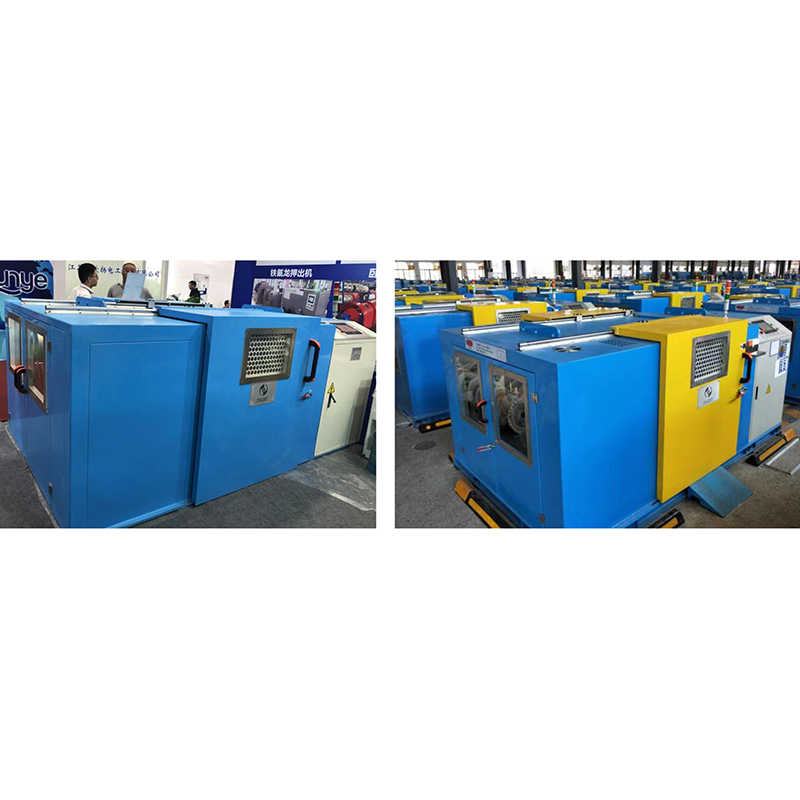 Triple Stranding Machine for CAT5E, CAT6, and CAT7 LAN CablesTriple-pitch stranding machine lays three twists per revolution, using servo pitch control for accurate, stable pair twisting in CAT5E, CAT6, and CAT7 data cables.View Product →
Wire Range, Conductor Construction and Closing Dies
A tubular strander is usually specified over a single-wire range of 0.15 mm to 3.0 mm and a finished conductor range up to about 630 mm², with the closing die and form rollers deciding how round or sector-shaped the finished conductor turns out.
- 0.15 mm to 0.5 mm: high rotor speed, low tension and ceramic guides are essential to avoid nicks and breaks.
- 0.5 mm to 1.5 mm: the general-purpose band for building wire, control cable and instrumentation conductors.
- 1.5 mm to 3.0 mm: power cable conductors and aluminium, where tension and braking ramp matter more than maximum speed.
- Compacting: a compacting die after the closing die typically reduces conductor diameter by 6% to 10%, which saves insulation compound downstream.
- Sector conductors: forming rollers ahead of the take-up produce sector shapes for large power cables, and they must be specified at order stage.
- Aluminium: softer than copper, so expect lower tension settings, gentler acceleration and a longer closing die to control surface quality.
Tension Control, Take-Up and Drive System Specifications
Tension control is where inexpensive tubular stranders fail: a machine that holds per-bobbin tension within roughly ±10% produces a concentric conductor, and one that does not produces broken wires, out-of-round sections and rejects at the insulation line.
Mechanical friction brakes with dancer rollers are the simplest option and are acceptable for coarse counts at steady speed. Pneumatic brakes and hysteresis brakes with closed-loop feedback hold tension better through acceleration and deceleration, which matters when a 36+1 rotor is ramping from zero to working speed. On the take-up side, check the taper tension range, the traverse pitch — normally set slightly wider than the conductor diameter so windings do not overlap — the length counter accuracy and the wire-break detection response. For the drive package, independent servo motors per rotor section with PLC recipe storage let an operator recall a construction instead of re-setting gears, and that shortens changeover from hours to minutes.
Tubular vs Bow, Planetary and Back-Twist Stranders
Choose the strander type by twists per revolution and package size: tubular for one lay per revolution at high speed, bow for two lays per revolution, planetary for large packages and high wire counts, and back-twist machines for data pairs.
| Machine type | Twists per revolution | Typical wire count | Typical conductor size | Best fit |
|---|---|---|---|---|
| Tubular (rigid) | 1 | 6+1 to 36+1 | Up to about 630 mm² | Bare copper and aluminium building, control and power conductors |
| Bow (double twist) | 2 | 2 to 12 | Up to about 120 mm² | Insulated cores, control and instrumentation cables |
| Planetary | 1 | 12 to 60+ | Above 630 mm² | Large power conductors, high wire counts, large bobbins |
| Back-twist pair | 1 per pair, with back twist compensation | 2 per pair | Up to about 6 mm² pairs | Data, LAN and paired-construction cables |
When a project moves above the tubular machine's comfortable range, the usual answer is a planetary strander, which carries more bobbins in a larger cage and trades rotor speed for package size and wire count.
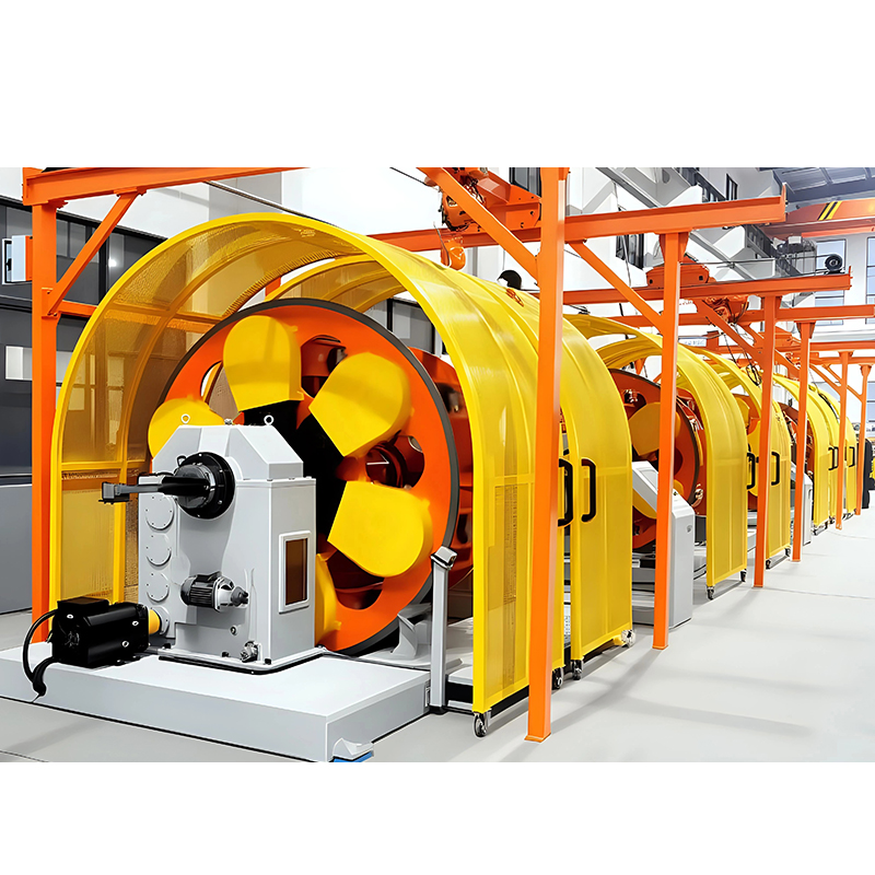 Planetary Type Stranding Machine for Complex High-Performance Cable CablingPlanetary stranding machine suits more bobbins and high core counts, using synchronous rotation and integrated shielding/taping for complex precision cables.View Product →
What to Verify at Acceptance Testing
Run the acceptance test with both an empty and a fully loaded rotor, because speed, tension and vibration errors only appear when the tube is carrying its maximum bobbin weight.
- Pitch accuracy: measure ten consecutive lay lengths on the finished coil and confirm they fall within the agreed tolerance, typically ±2%.
- Tension consistency: check every pay-off position with a tensiometer at running speed and log the spread across all positions.
- Speed under load: time a measured length at full bobbin weight, not at empty weight, and record the actual pitch used.
- Noise and vibration: readings below about 80 dB(A) at one metre and smooth tube rotation indicate good balance and bearing alignment.
- Sample conductor: test DC resistance, elongation, concentricity and surface finish, and compare against the pre-purchase sample.
- Changeover time: reload a full set of bobbins with your own operators and time it, because this is a daily cost.
- Documentation and spares: obtain wiring diagrams, PLC backup, a spare-parts list and confirmation of tension spring and ceramic guide availability.
Procurement Risks and Site Requirements
Most tubular strander projects slip on site and interface issues rather than machine performance, so settle power, foundation and bobbin standard before signing.
- Installed power: confirm the total load, voltage and frequency, and check whether the drive package needs a dedicated transformer or a soft starter.
- Foundation: ask for the bolt pattern, dynamic load figures and vibration isolation requirements; a 36+1 machine at speed will find a weak floor.
- Floor space: allow the tube length plus roughly 1.5 m at each end for bobbin loading and coil removal.
- Utilities: clean, dry compressed air for pneumatic brakes and a stable ambient temperature for tension repeatability.
- Bobbin standard: insist on compatibility with your existing PND or DIN bobbin fleet, because proprietary bobbins lock you into one supplier.
- Spare parts: tension springs, ceramic guides, closing dies and belts wear first, so agree lead times for these items in the contract.
- Safety and compliance: interlocked guards, emergency stops and the marking required in your market should be stated in writing.
- Data sheet traps: be suspicious of a line speed quoted without a pitch, and of tension quoted per machine rather than per bobbin.
FAQ: Tubular Stranding Machine Specifications
Is a tubular strander the same as a rigid strander?
The two terms are often used interchangeably, but tubular refers specifically to machines where the pay-off bobbins sit inside a rotating tube. Rigid stranding is the broader family and includes cage-type machines with a different rotor construction, so ask which geometry is being quoted.
What pitch range should I ask for?
For most bare copper and aluminium conductors, a working range of 20 mm to 300 mm covers nearly every construction, with the usable band for your product sitting in the middle. Specify the pitch range with the corresponding rotor speed so the quoted output is verifiable.
How many bobbins do I need for a 19-wire conductor?
A 19-wire concentric construction needs an 18+1 machine: eighteen rotating pay-off positions plus one central position for the core wire. A 12+1 machine can only build a 13-wire conductor, so the count has to match your largest planned construction.
Can a tubular strander run aluminium conductors?
Yes, provided the tension system is set low enough and acceleration is gentle. Aluminium is softer and more prone to surface marking, so expect slower ramp profiles, a longer closing die and more frequent guide inspection than with copper.
What line speed is realistic?
Realistic speed depends entirely on pitch. At a tight 30 mm pitch, a rotor at 900 rpm produces 27 m/min; at a long 200 mm pitch the same rotor reaches 180 m/min. Treat any single speed figure without a pitch as a marketing number rather than a specification.
Written specification work pays for itself. Put bobbin count, bobbin size, pitch range with the matching rotor speed, wire range, tension accuracy and pitch tolerance on one comparison sheet, then test those numbers against a live sample before the purchase order goes out. If you want to see how these figures translate into real machines, the range overview on the main catalogue page lists the stranding models and their bobbin sizes side by side.