

 English
 русский
 Español

Industry News
NEWS


Fiber Optic Cable Making Machine: Precision Production Essentials
2026-08-06
Content
- 1 Why Fiber Optic Cable Production Needs a Dedicated Equipment Line
- 2 Core Machine Types in a Fiber Optic Cable Production Line
- 3 The Stranding and SZ Cabling Stage: The Heart of Fiber Optic Cable Making
- 4 Choosing the Right Taping Machine for Optical Cable Core Protection
- 5 Sheathing and Jacketing: Final Protection for Optical Cables
- 6 How to Configure a Fiber Optic Cable Making Machine Line for Your Factory
- 7 Quality Control Equipment and Inspection in Optical Cable Production
- 8 Build a Reliable Fiber Optic Cable Production Line with the Right Equipment Partner
Why Fiber Optic Cable Production Needs a Dedicated Equipment Line
You cannot build a reliable fiber optic network using machines designed for standard copper power cables. The core reason is the physical nature of the glass fiber itself. A standard optical fiber has a cladding diameter of just 125µm, smaller than a human hair. While copper conductors can tolerate significant pull tension and minor surface abrasion during twisting, a glass fiber will snap or develop microfractures that lead to catastrophic signal loss, known as attenuation.
This fragility forces a completely different design philosophy on the production line. A fiber optic cable making machine must prioritize two factors above all else: sub-Newton tension control and dynamic bending radius management. In copper cable production, you might accept a tension fluctuation of several kilograms. In optical fiber secondary coating or stranding, your tension control system must maintain a steady pull often below 1 Newton. Any sudden jerk—caused by a worn belt in a capstan or an unsynchronized pay-off—will immediately register as a "point defect" on an optical time-domain reflectometer (OTDR).
The structure of the cable also dictates the machine type. A loose-tube cable requires an SZ stranding machine capable of precise fiber excess length (EFL) management. This EFL, typically controlled between 0.1% and 0.3%, ensures that when the finished cable stretches during installation in freezing conditions, the glass fiber floats within a gel-filled tube and remains stress-free. A central-tube design, conversely, places the fibers in a single core tube, placing higher demands on the sheathing line’s ability to extrude the jacket without crushing the ribbon stack. Using a rigid-frame strander without back-twist on a loose-tube design will twist the fragile tubes, causing unpredictable attenuation spikes. Dedicated optical cable equipment is not a luxury; it is a requirement to hit a 0.35 dB/km attenuation ceiling.
Core Machine Types in a Fiber Optic Cable Production Line
Mapping the journey of glass fiber to a ruggedized outdoor cable reveals a sequential chain of specialized stations. While the upstream preform and drawing tower processes create the bare fiber, the cable manufacturing line begins where the finished fiber spools are loaded. Understanding this sequence allows you to identify bottlenecks and verify that a proposed configuration is complete.
The standard workflow moves through four distinct zones:
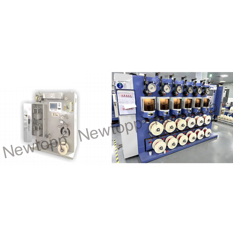
- Fiber Coloring and Buffering: High-speed coloring machines apply a stable UV-cured ink layer for identification. For tight-buffered indoor cables, a tight-buffer extruder applies a thick thermoplastic jacket directly over the optical cladding.
- Ribbon Forming: For high-fiber-count cables, ribbon forming machines bond 4, 6, or 12 fibers side-by-side with a UV-acrylate matrix. This creates a flat ribbon stack, maximizing fiber density in a small core tube.
- Core Stranding and Taping: This is the central architecture phase. SZ stranding machines oscillate loose tubes around a central strength member, creating a helical pattern. Immediately after, a taping machine wraps the core with water-blocking tape and polyester binding yarn to hold the geometry.
- Inner and Outer Sheathing: The final barrier. A nylon or polyethylene inner jacket is extruded, aramid yarn strength members are applied, and a final thick polyethylene outer jacket—often high-density polyethylene (HDPE) or medium-density polyethylene (MDPE)—completes the ruggedized package.
Each transition between these machines demands a multi-dancer accumulator. The accumulator acts as a dynamic buffer, letting the stranding line run continuously while a sheathing line operator splices a new tape pad or replaces a reel. Without careful management of these transitions, the line speed collapses to the speed of the slowest manual operation.
The Stranding and SZ Cabling Stage: The Heart of Fiber Optic Cable Making
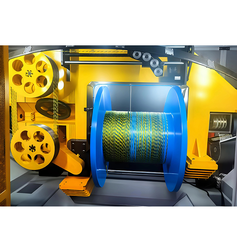
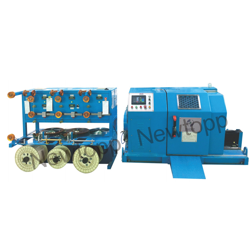
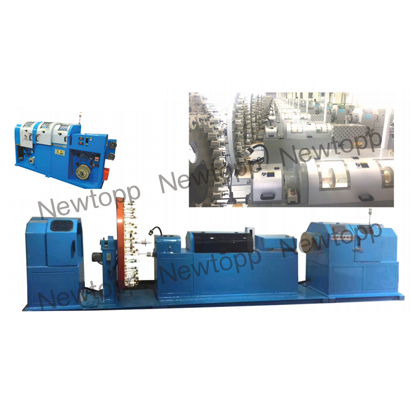
Stranding for optical cables is distinct from telecom copper pair stranding because the process oscillates rather than rotates continuously. If you are new to the terminology, a comprehensive guide to cable stranding machines helps establish the basics, but SZ stranding is the foundation of loose-tube optical design. Instead of a rotating pay-off that requires massive slip rings, the fiber buffer tubes feed from stationary spools. Guide discs oscillate clockwise and counterclockwise at predefined pitches, typically between 60 and 300mm, laying the tubes into the helical grooves of a strength member.
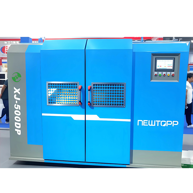
Your selection criteria here must focus on back-twist elimination. A planetary type stranding machine for optical cable core achieves this through synchronized gearing that cancels the twist on each element. In an SZ planetary unit, the tubes rotate around their own axis to stay parallel to the machine floor, ensuring no torsional rotation is induced in the tube itself. This prevents the 12 fibers inside from being bundled into a stress mass. The machine must allow you to control the fiber excess length (EFL) through precise capstan speed differentials in the lay plate area. A deviation of just 0.1% in EFL can shift the cable’s temperature stability window by 30°C, causing massive attenuation at low temperatures.
Equally critical is the tension. If a pay-off motor overshoots its torque on startup, the bounce will vibrate the 125µm fiber with a shockwave, causing a micro-bend. High-quality stranding lines use closed-loop tension dancers with laser-micrometer feedback. These systems reject disturbances within microseconds, maintaining a constant lay geometry even if the line accelerates from zero to 60 meters per minute in seconds. For smaller volume runs requiring precise pairing, back-twist pair twinners ensure that the data pairs remain perfectly parallel without the spiral stress that degrades bandwidth in pre-connectorized drop cables.
Choosing the Right Taping Machine for Optical Cable Core Protection
The zone immediately after the SZ strander is a containment battlefield. The oscillated tubes want to spring apart. Water-blocking is legally required for outdoor cables to prevent longitudinal water migration inside the conduit. This is the realm of high-speed precision taping.
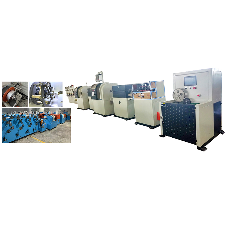
You face a choice between longitudinal application of swelling tape and helical wrapping of binding yarn. A non-woven water-swellable tape is typically fed longitudinally with an overlap, forming a sock around the core. A CNC servo taping machine for multi-layer wrapping handles the subsequent stage, applying a polyester binding tape with an interlaced or gap-lapping technique. The key metric here is overlay consistency. If the set tape overlay is 15%, a mechanical brake system might oscillate between 5% and 25% as the pay-off spool empties and rotational inertia drops. This leaves the core loose.
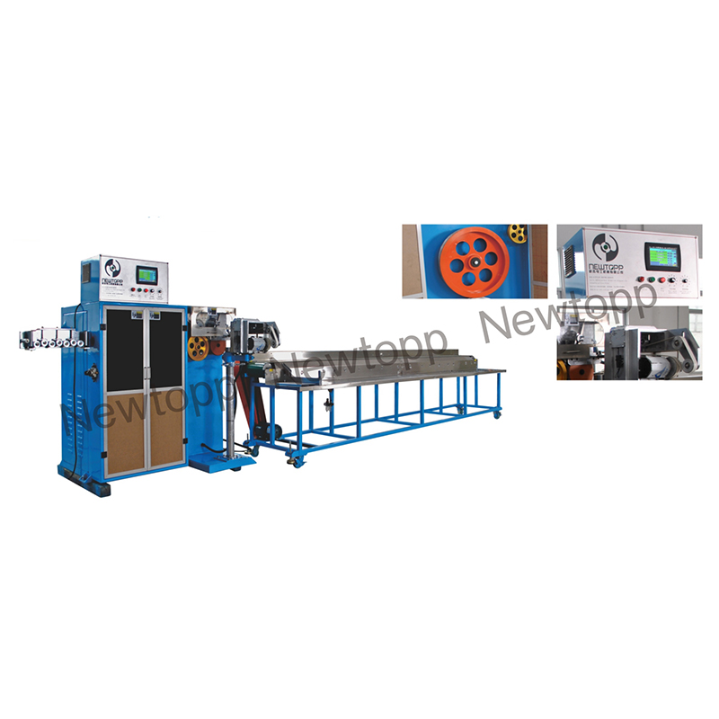
A servo-controlled CNC taping machine calculates the spool’s decreasing diameter in real-time, adjusting motor torque to keep the pay-off tension linear. This is vital for water-blocking performance. If the tape is too loose, water channels form in the corrugations. If too tight, the tape bites into the buffer tubes, compressing them and inducing fiber strain. The taping head must also run in perfect synchronization with the linear line speed. A lag of milliseconds causes a twisting bunch-up that will eventually pierce the inner sheath. For high-density cables, dual-layer taping heads apply a counter-helix wrap, locking the first layer in place and creating a perfectly round, rigid core ready for jacketing.
Sheathing and Jacketing: Final Protection for Optical Cables
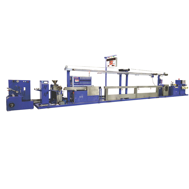
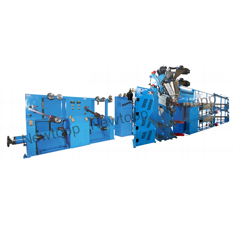
The sheathing stage transforms the delicate tape-wrapped core into a submersible, UV-resistant product. A standard power cable extrusion line lacks the gravimetric control and shrinkage compensation needed here. For a deeper look at the precision mechanics involved, this overview of precision cable extrusion equipment explained breaks down the critical components. When you move to optical cable, you require a dedicated cable jacket sheath extrusion line for final protection with specific modifications.
The primary difference is post-extrusion shrinkage management. HDPE contracts significantly as it cools from 220°C to ambient room temperature. If the jacket contracts faster than the core, it compresses the fiber tubes, causing a massive attenuation spike called "shrink-back attenuation." To combat this, the line must be configured with a fiber excess length control system before the crosshead. A dancer assembly pre-feeds the core at a slightly faster rate than the payout. Simultaneously, the cooling trough uses segmented temperature zones, starting with warm water at 60°C to anneal the plastic, stepping down gradually to 20°C. A single-trough cold-water dunk shocks the plastic, creating amorphous crystalline structures that shrink unpredictably in the field.
Wall thickness control is another optical-specific demand. An eccentric jacket creates a preferential bending axis. When a lineman kinks the cable during installation, a thin wall crushes the strength member onto the fibers. A tri-axial centering crosshead with a hot-centering control loop ensures concentricity above 95%. The temperature control of the barrel zones on the extruder must hold within ±1°C. A temperature overshoot degrades the low-smoke zero-halogen (LSZH) compounds commonly used in indoor riser cables, creating char particles that scatter light and cause mura defects on the jacket surface. The final hot-stamping ink-jet prints the meter marking at speed, completing the ruggedized package.
How to Configure a Fiber Optic Cable Making Machine Line for Your Factory
Configuring a line is an exercise in eliminating mismatch. Your goal is to stop the fastest machine from dragging the slowest one to a stop. You start by specifying your core product: a loose-tube duct cable for inter-city backbone, a central-tube microcable for conduit packing, or a flat drop cable for FTTx (Fiber To The Home). A loose-tube line demands an SZ strander, dual tape binders, and a thick HDPE sheathing line with an aramid yarn servo server. A central-tube line simplifies the stranders out of the picture, but demands a much more sophisticated extrusion crosshead capable of extruding over a vibrating ribbon stack without melting the matrix.
Line speed parity is the trap every new investor hits. A modern coloring machine can run at 2,500 m/min. Your SZ strander might max out at 100 m/min. You cannot feed a 2,500 m/min machine with the output of a one-meter accumulator. You must define a target effective line speed, often 80 to 160 meters per minute for a mid-capacity plant, and spec all downstream accumulators to provide at least 180 seconds of buffer at that speed. This lets operators change raw materials without tripping the entire line. You also cannot neglect the utility infrastructure: the required compressed air dew point for pneumatic tensioners is -40°C. A standard shop air system with water vapor will seize the precision regulators inside a week. Your factory configuration must list the machine, the connecting bridges, and the utilities as one system debt, not separate afterthoughts.
Quality Control Equipment and Inspection in Optical Cable Production
Invisible defects accumulate silently in optical cable. By the time you find them on a final reel OTDR test, you may have already packaged five kilometers of scrap into a wooden drum. Online, in-process quality control is non-negotiable and belongs between each major machine stage.
You need three gatekeeper systems: laser micrometers, lump-neck detectors, and distributed tension loggers. A laser micrometer positioned just after the tight-buffer extrusion screw instantly flags a 5µm diameter deviation, indicating a screw surge. A lump detector in the cooling trough catches internal jacket voids—pockets of unmelted gel that will crush the fiber under frost. The most vital, though, is the tension traceability system. By logging the pay-off tension from every single fiber bobbin entering the SZ cages, you can pinpoint that a spike in attenuation on drum 4 originated from a sticky bearing on fiber position 4B at kilometer 1.2. Without this traceability, you shut down the line for days swapping out bearings indiscriminately.
At the final take-up, a laser-based surface defect inspector spins around the jacket at 360 degrees, algorithmically identifying pinholes, shrinkage rings, and gauge bands before the winding tension wraps them into the cable drum. These systems reject defects in tens of microseconds, marking the jacket for manual excision later. RTD (Resistance Temperature Detector) probes in the melt pump ensure no barrel zone drifts by more than a degree, preventing the silent gel contamination that scatters light and raises attenuation floor values across the entire production lot.
Build a Reliable Fiber Optic Cable Production Line with the Right Equipment Partner
The paper specifications of a machine mean very little if the supplier cannot integrate the total line. A 100 m/min SZ strander connected to a sheathing line through a poorly tuned dancer becomes a 40 m/min line. The true value of your investment pools in the interface engineering and the process startup support. You need a partner whose engineering bench covers the major blocks of the optical cable chain: stranding, taping, and extrusion. A supplier who only builds stranders will blame the extruder for a lay fluctuation, and vice versa. A vertically capable team owns the problem from the pay-off to the take-up, tuning the entire PID loop so that the extrusion tractor capstan whispers to the SZ cage rather than yanking it.
The manufacturing DNA of a precision equipment builder, such as Jiangsu Newtopp precision cable machinery manufacturer, is built on delivering solutions where the mechanical tolerance of a gearbox or the thermal isolation of a barrel zone translates directly into a production yield percentage. You are not just buying steel and motors. You are buying a guarantee that the fiber excess length remains between 0.2 and 0.5 per mil after a one-shift thermal soak, and that the jacket concentricity holds at peak line speed. When the turnkey project hands over, your technician should know exactly which parameter dial to turn when a seasonal humidity change shifts the water-blocking tape friction coefficient. This is the difference between a machine that occupies floor space and a machine that ships acceptable cable.
-
Phone
+86 188 2296 5630 +86-(0)515-8510 8601Email
[email protected]
[email protected]
[email protected]
[email protected]
[email protected]
[email protected]Address
No. 168 Haitai Road, Dongtai City, Jiangsu Province, China
Copyright © 2025 Jiangsu NewTopp Precision Machinery Co., Ltd. All Rights Reserved. Wire & Cable Equipment Manufacturer
Robot Cable Production Ancillary Equipment Factory
